


In this blog post, I will show you how to properly control an LEDs brightness using PWM . It isn’t as simple as you think!
PWM works by varying the duty cycle of a square wave, like so:
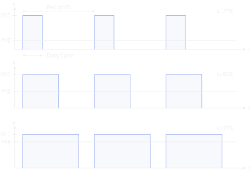
The effective voltage is equal to VCC * k (where k is the Duty Cycle), and for an LED its
brightness will also be proportional to k (Assuming it is driven with a constant current and voltage).
Pretty much every microcontroller supports PWM, either through a dedicated peripheral,
or you can do it yourself in software!
However, there is a problem with the common approach of PWMing an LED. Take this Arduino code for example:
void loop() {
    byte i = 0;
    while (1) {
        analogWrite(2, i);
        delay(10);
        i++;
    }
}
This will fade an LED on pin 2 of the arduino, from dark to bright. But you may notice the LEDs don’t fade very nicely. They will appear to fade very quickly at first, and then spend a long time at full brightness:

The reason behind this is because the human eye doesn’t respond to light linearly, but logarithmically. That sure complicates things!
To fix it, we have to correct the PWM values to make them appear linear to the human eye.
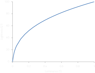
A common misconception is that gamma correction should be used, as it does have a very similar response to the eye. However, gamma correction has nothing to do with how humans perceive light, it is just coincidence that it appears to work. The CIE 1931 lightness formula is what actually describes how we perceive light:
L* = 903.3 ∙ Y,            if Y ≤ 0.008856
L* = 119   ∙ Y^1/3 – 16,   if Y > 0.008856
Where Y is the luminance (output) between 0.0 and 1.0, and L* is the lightness (input) between 0 and 100
The formula needs to be rearranged in terms of L*:
Y = (L* / 903.3)           if L* ≤ 8
Y = ((L* + 16) / 119)^3    if L* > 8
Of course, this formula would be too slow to implement on a microcontroller due to the power and division, so you should use a look-up table instead. I created a simple python script to generate a C header file that can be simply included into the project:
INPUT_SIZE = 255       # Input integer size
OUTPUT_SIZE = 255      # Output integer size
INT_TYPE = 'const unsigned char'
TABLE_NAME = 'cie';

def cie1931(L):
    L = L*100.0
    if L <= 8:
        return (L/903.3)
    else:
        return ((L+16.0)/119.0)**3

x = range(0,int(INPUT_SIZE+1))
y = [round(cie1931(float(L)/INPUT_SIZE)*OUTPUT_SIZE) for L in x]

with open('cie1931.h', 'w') as f:
    f.write('// CIE1931 correction table\n')
    f.write('// Automatically generated\n\n')

    f.write('%s %s[%d] = {\n' % (INT_TYPE, TABLE_NAME, INPUT_SIZE+1))
    f.write('\t')
    for i,L in enumerate(y):
        f.write('%d, ' % int(L))
        if i % 10 == 9:
            f.write('\n\t')
    f.write('\n};\n\n')
Which produces a table that looks like this:
const unsigned char cie[256] = { 0, 0, 0, 0, 0, 1, 1, ..., 247, 250, 252, 255 };
Depending on the microcontroller being used, you may want to change the type so it stores the values in ROM instead of RAM.
The constants at the top can be changed to suit the microcontroller. For instance, if you wanted to use a 10 bit PWM,
you could set INT_SIZE=1024. This would still generate a table with 256 entries, but the output will be 10 bits.
Because this conversion reduces the resolution of the PWM, it may indeed be wise to use a 10 bit PWM. This is exactly what I did in my LED Coffee Table Project .
Finally, using the lookup table to fade LEDs:
#include "cie1931.h"

void loop() {
    byte i = 0;
    while (1) {
        analogWrite(2, cie[i]);
        delay(10);
        i++;
    }
}

Thanks to all the comments below for helping with errors in my original article!
Also see this C++11 constexpr version by nitz