
I’ve always been interested in the idea of re-using old laptop LCDs, but it always seemed out of my reach until recently I had a huge urge to wire up a special sunlight-readable Portege R500 “transflective” LCD…
In this project I’ll show you exactly how I was able to reverse-engineer an LCD panel and get it to work with an LVDS-equipped linux board. If you want to know more about the details, you should check out my article on Driving FPD-Link Displays .
The biggest problem in re-using an old laptop LCD panel is that the panels do not use a standard protocol like HDMI or DVI, so they cannot be directly hooked up to a computer. Instead they use a protocol called “FPD-Link”, commonly referred to as LVDS (Low Voltage Differential Signalling). Fortunately LVDS is very similar to HDMI/DVI, and all that is required is a small HDMI-to-LVDS converter board.
The RIoTBoard
To make things easier I purchased a RIoTBoard SBC, which features native LVDS outputs! It’s worth noting that it only has a single channel 18bpp LVDS output (even though the i.MX6 chip itself supports two 24bpp channels), which means it can’t drive anything higher than approximately 1280x800 through the LVDS connector.
 RIoTBoard SBC
It is fairly similar to the Raspberry Pi, featuring USB, ethernet, HDMI, and an integrated GPU for hardware-accelerated graphics and video. Eventually I plan to write my own GUI application that will run on the RIoTBoard with some attached laptop LCD panel.
First LCD Panel
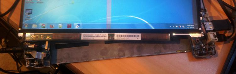
Because the R500 LCD has a rather tricky connecter, I wanted to make sure I could get LVDS to work with a simpler panel first. I chose a random laptop out of my collection and extracted the panel:
 Stack of laptops
 Extracted panel
The next step is to locate the LVDS pairs and the power wires, but I saved myself the trouble of reverse-engineering the exact pinout and managed to find a datasheet floating around on the internet.
The flurorescent backlight driver proved to be a bit more tricky but a bit of probing around revealed the correct connections.
Tip: When searching for datasheets, look for part numbers on the LCD and search google for:
"PARTNUMBER filetype:pdf"
From there it was a simple matter of wiring the LVDS cable and hooking it up to the RIoTBoard:
 LVDS wiring
 RIoTBoard connected to LCD
Note: The micro-HDMI connector on the RIoTBoard is actually LVDS, not HDMI!
Portege R500 LCD
On to the real challenge!
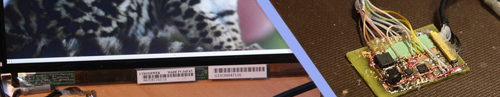
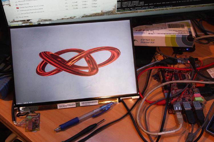
 Portege R500 LCD - LTD121EWEK
The LCD pictured to the right is a special panel made for the Toshiba R500/R600 laptop series, which allows the laptop to be used outdoors in full sunlight. I had a few of these laptops spare, and I thought it could be useful in my own projects, so I decided to have a try at getting it to work with my board.
Here is the datasheet: LTD121EWEK (R600 model)
The panel takes 2.5V, and has an LED backlight which requires about 30V. It has a resolution of 1280x800, and has a single FPD-Link channel (3 data lines + 1 clock).
Reverse Engineering
Initially I couldn’t find a datasheet for the panel (although I did find one later!), so I started by attempting to reverse engineer the laptop panel to work out the correct pinout. I did this by careful observation of the PCB layouts, and by probing the panel in a live system.
 Probing signals in a live laptop
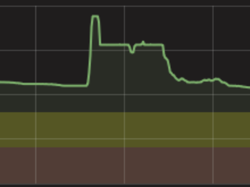
 Corrupted red data channel in a live laptop
The LVDS pairs were fairly obvious on the laptop motherboard, but figuring out which one was which was a bit more tricky. I actually found out I could squeeze the wires and it would cause the display to become corrupted, and by comparing the colours on the display with the FPD-Link packet format I was able to determine the 3 data channels and 1 clock channel! The clock LVDS pair was the easiest to find, as the display simply freezes or goes black when it loses the clock.
When I found the datasheet later on, I compared it with my findings and I was actually very close - I had missed the EDID signals, and had the polarity of the LVDS signals reversed. Not bad! Having EDID signals also means I can make the display “plug’n’play” with pretty much any system, meaning the computer will be able to automatically detect the correct resolution and panel type.
Break-out Board
 3D rendering of breakout PCB
The next stage was to find a way to connect the display to my RIoTBoard, which wasn’t easy due to the extremely fine wiring. Initially I tried to use the existing LCD cable to solder to, but it turns out the wires are actually very small micro-coaxial cables, and soldering them causes a dead short to ground!
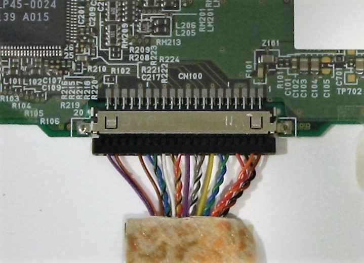
So I decided to develop a breakout board using the same connector as on the laptop motherboard, including a backlight driver based on the same chip as the laptop motherboard. (I couldn’t actually find a place to buy the connector, so I just extracted one from a dead laptop)
I decided I would try to etch the PCB at home to see if it was actually possible. The PCB ended up being a big test of my skills, as it included some incredibly fine traces (the LVDS traces are 0.254mm wide!)
It took me 4 attempts to actually get the iron-on toner transfer to stick properly, but eventually I was able to get an almost perfect transfer! My first etch wasn’t successful though - it ate right through my thin LVDS traces!
 Etched PCB in Ammonium Sulfate
 Two attempts at etching the PCB
Tip: Don’t over-saturate your Ammonium Persulfate solution - it doesn’t make it etch faster, in fact it prevents any etching from happening at all! I had to dilute my solution with water before it actually did anything.
After soldering everything up I powered it up and attached it to my RIoTBoard, and amazingly an image appeared on the screen! (Although note that the image doesn’t quite completely fill the display)
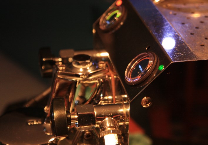
 Initial testing of breakout board
Final Solution
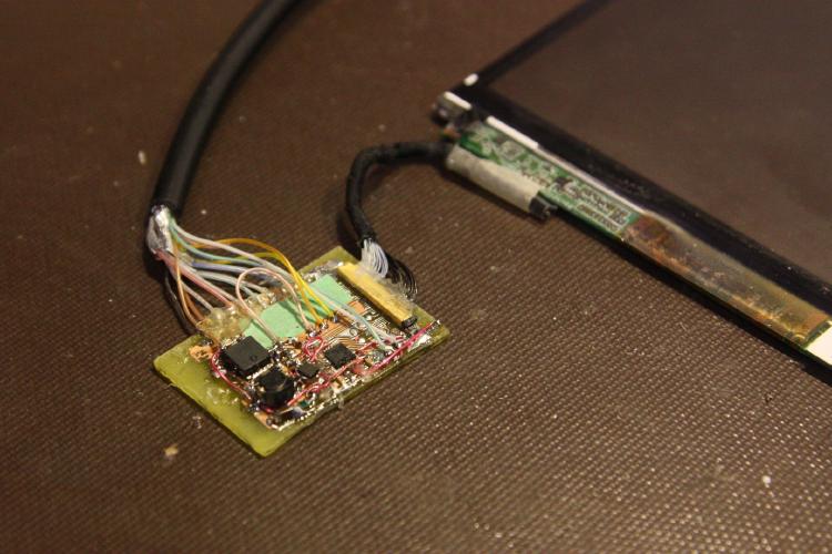
The final step of the project was to implement the backlight driver. This proved to be a lot trickier than I thought due to the high operating frequency (0.5-1.0MHz), making the circuit unstable and causing components to heat up. After a bit of trial and error I eventually found an appropriate MOSFET, diode, and inductor that worked.
The final breakout board is pictured below:
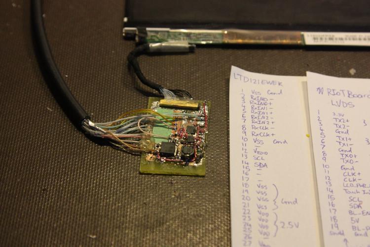
As for the RIoTBoard, some configuration was necessary to get it to output the correct resolution, as the linux kernel doesn’t seem to pick up the EDID information (although I can dump it through the i2c-read program). This is done by entering the U-Boot console on boot and modifying the video bootargs:
Hit any key to stop autoboot...
U-Boot
> setenv bootargs console=ttymxc1,115200 init=/init nosmp video=mxcfb0:dev=ldb,1280x800M@60,bpp=32 video=mxcfb1:off fbmem=10M
> saveenv
In the above configuration, video is modified to use the ldb output and set to a resolution of 1280x800 with reduced blanking (M)
Conclusion
The project was a success! I was able to get a very tricky LCD panel working with a linux board, complete with a home-etched breakout PCB! Now to figure out what to use it for…