One day I was browsing our local buy and sell marketplace and came across a vintage E61-style espresso machine for a good price, and saw my opportunity to absorb myself into a project for the next few months…
I had actually been thinking about stepping up my espresso game for a while, having not been very satisfied with the Breville machine I’d been using to caffeinate myself each morning. I knew what good coffee could taste like, and suspected the machine was the limiting factor. Also I was itching to start a new electronics project.
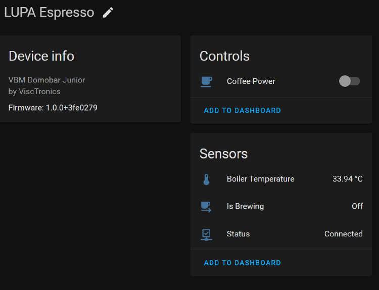
And so became Lupa Espresso - a modification of the Vibiemme Domobar Junior (HX) espresso machine, adding PID heat control, Home Assistant integration, digital displays, and shot diagnostics.
While this project is pretty specific to the Vibiemme Domobar espresso machine, the firmware and PCB could probably be re-purposed for other similar machines…
The Machine
 Vibiemme Domobar HX
The VBM Domobar is electrically very basic, though the mechanics are quite smart. It belongs to a class of espresso machines that all derive from a common “E61 grouphead” design.
Hot water is provided via a heat exchanger and internal boiler, and is pressurized with a pump. There is a small control board that fills the boiler as needed. Two analog pressure gauges show the boiler and grouphead pressures.
The only electrical control is a single external lever that activates the pump, allowing you to pull a shot. The mechanical design does the heavy lifting and provides pre-infusion, pressure release, etc.
Temperature is maintained by a “pressurestat”. This results in an unsteady temperature in the boiler as the pressure rises and falls, but the large thermal mass helps balance things out. I intend to replace this with a better PID control loop.
Design Direction
The most important part of any project is to figure out the requirements and goals.
I have a fully functional machine that makes good coffee, and I don’t want to regress that… But I would like to add smarts to it through digital sensors and displays.
Requirements
- PID temperature control
- Pressure transducer for monitoring brew pressure
- Temperature sensor for monitoring brew temperature
- Timer for measuring brew time
- Flow meter for measuring brew volume
- Digital display readouts that maintain the analog look and feel
- WiFi connectivity for remote startup
- Only physical inputs should be the lever and a power button
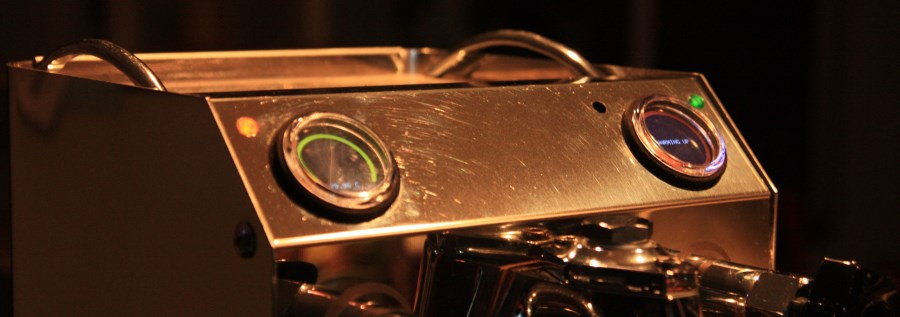
Furthermore it would be a huge shame to ruin the look of the machine, so I want to maintain the analog look and feel by using round LCDs and utilizing the existing lever for control.
I actually came across these round LCDs in another open-source project, and immediately recognized they would be a great fit for this project. In fact they perfectly fit where the analog pressure gauges would go in my machine!
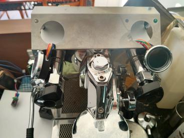
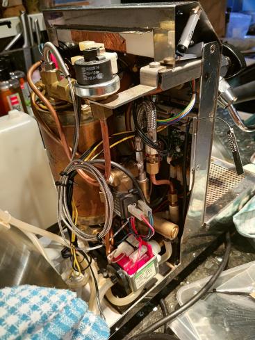
Disassembly
Let’s pull it apart and see what we have to work with! 😃
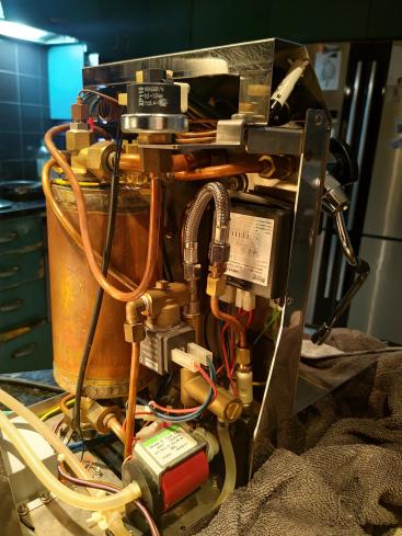
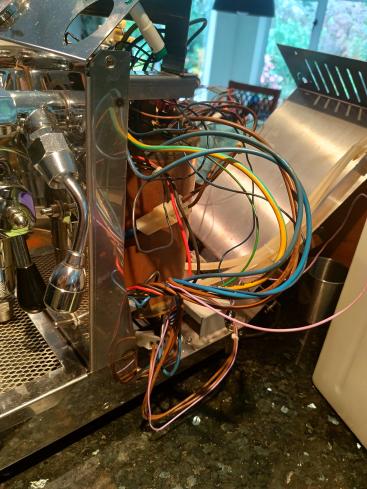
Fortuantely it’s not too packed and looks like it should be easy enough to modify.
Already I can see I’ll need to swap out the black controller box with something of my own design, and replace the analog pressure gauges with digital ones.
Also hidden away at the bottom of the unit is an SSR for the main boiler, which makes this very easy to control!
Thermocouple
In order to add PID boiler control we need a way to monitor the temperature of the boiler and grouphead. There are multiple places we could add a thermocouple, but I decided the best place would be in the path of the heat exchanger so the grouphead would have a more controlled temperature.
This does mean the boiler itself will have a more varied temperature, but it is not used directly for brewing so this is okay. The grouphead temperature itself is also difficult to directly measure since it is external to the machine and consists of a big chunk of brass metal.
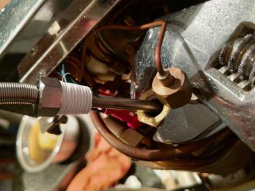
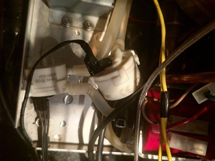
I found these neat thermocouples on AliExpress which have the right threading and are fully sealed, so I can just remove an existing pressure line and screw it right into the boiler tank (using teflon tape since this will be under pressure!):
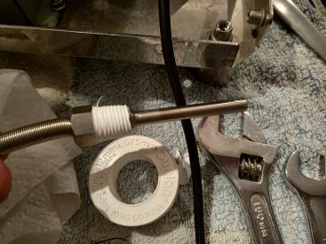
But wait before we do that, we need to calibrate it…
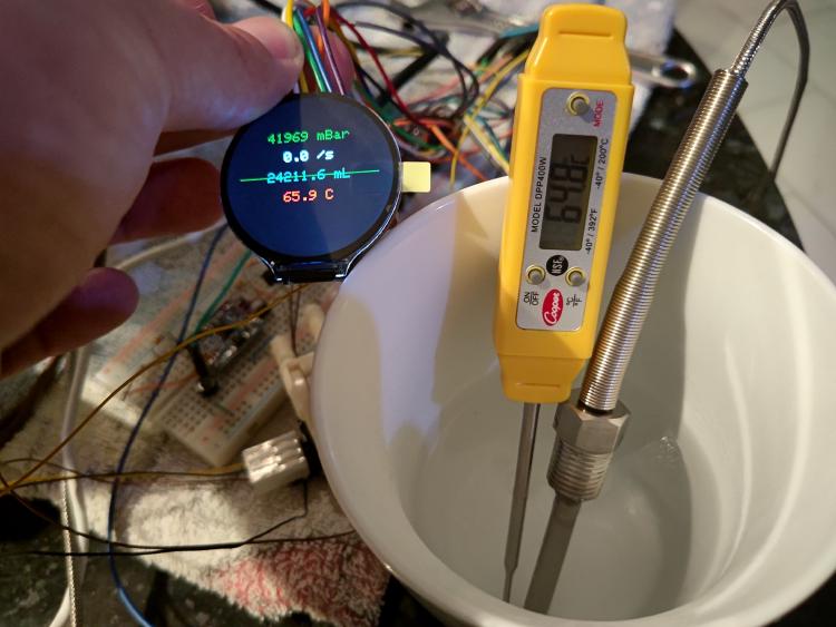
This procedure just involves placing the probe into a cup of water with ice cubes (~0C) or putting it into a jet of steam coming from a kettle (~100C) along with an already-calibrated temperature probe.
We can then use these two datapoints to form a linear correction of the raw RTD reading. It’s important to collect and average enough datapoints to ensure good accuracy.
Pressure Transducer
The brew pressure is not part of the control loop, but it is still useful to monitor it so we can see if the shot is progressing properly. In the future it opens the possibility of pressure profiling control as seen in much more advanced espresso machines…
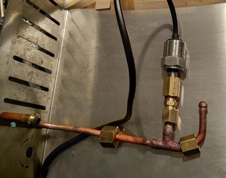
For this I found some very nice threaded pressure transducers, who the seller kindly sold me with an I2C interface and 0-12 Bar range (a typical espresso shot is 8-10 Bar).
Unfortunately I couldn’t work out a good place to mount them, since they need to be in the high pressure plumbing and I was running out of vertical headroom.
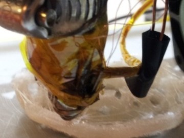
I opted for some light surgery with an oxy-acetylene welding torch:
Flow Measurement
Measuring the flow of water helps detect if a shot is progressing properly, and also opens the possibility of flow profiling control.
The best place to insert these is in the water intake and return lines, before the system becomes pressurized.
Unfortunately I had to use two flow meters, since the pressure regulation results in a constant flow of water through the return line that has to be accounted for.
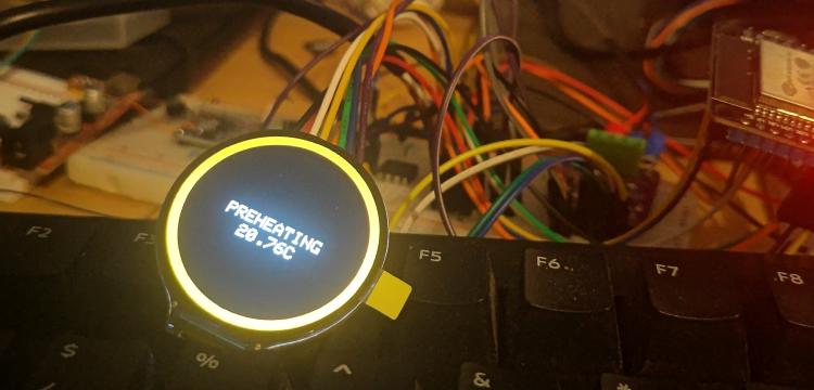
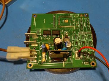
Prototype Hardware
With the two sensors above, the SSR for the boiler, and the round LCDs, I can start to put together a functional prototype using the ESP32 for control:
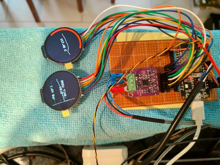
The readouts above show a real temperature and pressure reading from the machine.
And yes, I can still brew a coffee!
Displays
I care a lot about the look and feel of my designs, and so at this point I started working on my UX:
- The two analog pressure gauges will be replaced by two round LCDs
- The left display will show temperature and boiler status
- The right display will show brew/shot information
- A round arc will be used to mimic the feel of an analog gauge
- A graph will be shown in the background to show historical data
- Screens will switch depending on the current state of the machine
With a kind donation from PCBWay, I 3D printed brackets for the displays so they would fit into the metal chassis:
 Yes, Blender can be used for CAD...
 Printed in high-accuracy high-temperature nylon glass fiber
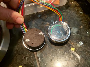
Firmware
The firmware has evolved quite a lot since the start of the project, so I’ll just cover some of the most interesting design elements.
State Machine
The core of the firmware revolves around a State Machine, roughly separated into the following states:
- Off/Sleeping
- Preheat
- Ready/Post-brew
- Brewing
- Error/Faulted
The advantage of using a State Machine is that we can formally define which inputs will cause the device to transition to a specific state, and define what will happen on this transition.
For example, the Preheat->Ready transition will only happen once the temperature rises above a defined threshold.
PID Control Loop
The PID algorithm is modified from br3ttb/Arduino-PID-Library utilizing float instead of double, and adding some extra features for perturbing the output when we know the temperature should start dropping.
The PID is fed into a software-PWM that turns the boiler SSR on and off at an interval of ~5 seconds. This reduces EMI from the ~2kW heating element. (Imagine switching 2kW at 20kHZ! Your local HAM hobbyists will hate you!)
I haven’t spent much time tuning the control loop, but already it works pretty well.
Sensor Filtering
One of the trickier parts of the firmware is filtering dirty sensor inputs…
To implement this we use Finite Impulse Response (FIR) filters, which is just a fancy way of convoluting the incoming sensor signal with a set of coefficients. The coefficients can be calculated with a handy online tool:
https://wirelesslibrary.labs.b-com.com/FIRfilterdesigner/
Annoyingly there is a fine line between latency (phase) and smoothness (gain), so we have to sacrifice one for the other. And since the system has a fair amount of noise, I end up with a latency of about half a second, which is borderline okay in terms of feedback.
So how do you actually implement a FIR filter? Convolution really just means multiplying two arrays together with one of them being reversed, so this ends up being pretty simple:
float output = 0;
for (int i = 0; i < lengthof(taps); ++i) {
    output += samples[lengthof(samples) - i - 1] * taps[i];
};
In practice the samples array should be a circular buffer, and should be the same size as the number of taps.
See my source code (fir.h
) for a full implementation.
I’ve also found that you need a minimum of 11 or 21 taps to get decent filtering performance. Any less, and the output is too unstable.
UI Rendering
(UI.cpp )
I developed a simple UI toolkit that operates in immediate-mode (ie, the UI is completely re-drawn on every frame).
To avoid flickering, I render first to an in-memory buffer before flushing to the display (“Double Buffering”).
With the ESP32, and a 80 MHz SPI frequency, I get about 10 FPS, which is honestly more than I was expecting.
WiFi & OTA
(Network.cpp )
This is why I have fallen in love with the ESP microcontrollers - connecting them to a network is a piece of cake!
There’s nothing too tricky going on here, I’m just using standard ESP-Arduino libraries to set up the WiFi and provide over-the-air (OTA) firmware updates.
HomeAssistant Integration
Since we have WiFi & MQTT, it’s fairly easy to connect it to HomeAssistant, especially since I had previously made a C++ template helper exactly for this purpose:
https://github.com/jorticus/hacomponent
WiFiClient          wifi;
PubSubClient        mqtt(wifi);
ComponentContext    context(mqtt);

HAComponent<Component::Sensor> sensor_temperature(context,
    "boiler_t",
    "Boiler Temperature",
    sensor_sample_interval_ms,
    0.0f,
    SensorClass::Temperature
);

void onMqttConnected() {
    HAComponentManager::publishConfigAll();
}

void report_temperature() {
    // Report current boiler temperature to HomeAssistant
    if (SensorSampler::isTemperatureValid()) {
        auto t = SensorSampler::getTemperature();
        sensor_temperature.update(t);
    }
}
PCB Design
With the prototype hardware well tested, it’s time to create a PCB so it looks like it won’t kill me while I’m using it.
In addition to the temperature/pressure/flow control that the prototype does, we also need to reimplement the automatic water-fill feature and interface and control the pump.
Water Level
The water level sensor consists of just a rod suspended in the boiler. I found that using the ESP32’s capacitive touch feature worked great for this.
Solenoid/Pump control
Since the solenoid and pump operate at mains voltage, we need a safe way to control these from the ESP32.
I found the AQH1213A chip that combines an opto-isolator, a TRIAC, and a zero-crossing detector all in one neat package!
The zero-crossing detector is important for AC loads, so that we avoid large current spikes due to turning on the load in the middle of the AC waveform.
Power Supply
I always find this part a little tricky - something that seems so simple (I just need to provide a little bit of juice for my MCU…) can become quite complex to design…
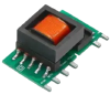
Fortunately I came across these SMPS modules that do the heavy lifting and only require a few passives to function…
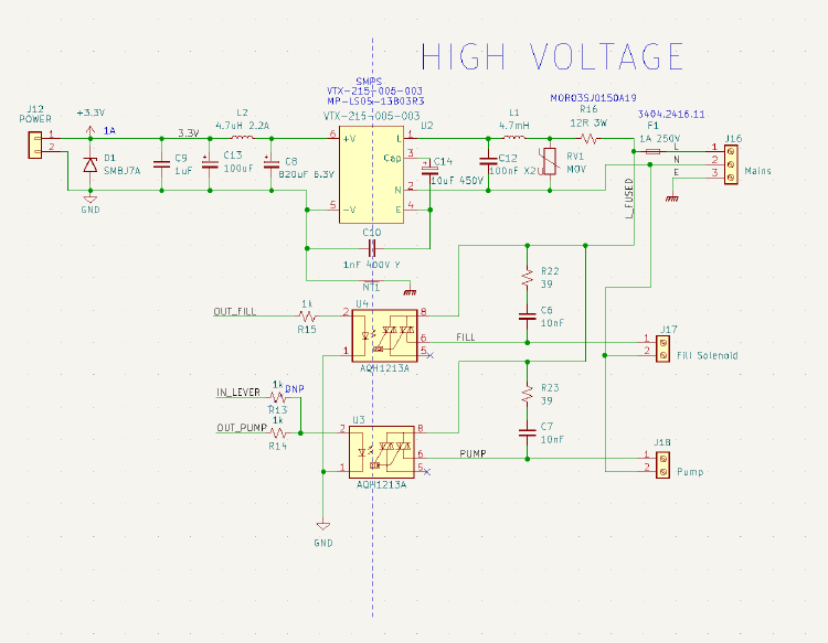
This means I can avoid having to dig too deeply into mains SMPS design (especially having to find the correct transformer!)
Important: don’t forget a fuse! And treat mains with respect.
Inputs and Outputs
This part of the design isn’t all that interesting, and just consists of a number of connectors mapped to the GPIOs of the ESP32.
I included some basic noise suppression through an R/C network on each input, as I know this will be in a fairly electrically-noisy environment. This forms a filter that should cut out any high frequency transients.
A more robust input protection circuit would include TVS suppression diodes as well…
It’s suprising how quickly the costs of connectors add up though! It actually took me a considerable time to select a low-cost connector, and I eventually settled on a variant of JST-XH.
One of the other annoyances in selecting connectors is I could only find ones with a minimum order quantity of 10 (some variants even had a minimum of 1000!). So to save cost, I decided to use 4 pin connectors for my sensors that only needed 3 pins, leaving 1 pin unused. This saves me from having to buy another set of 10.
This kind of cost-saving measure is actually used in mass-produced consumer goods, where the cost of setting up the factory line for each component is not insignificant. Often manufacturers will choose the same value of resistor (eg. 10k) everywhere instead of a mix of (1k, 4.7k, 10k, 20k), and then just parallel them up to get to the right resistance.
Assembly
With another donation from PCBWay, I ordered my finished PCB:
(I’m always impressed at their speed, it takes just over a week including the shipping to get it all the way over to New Zealand)
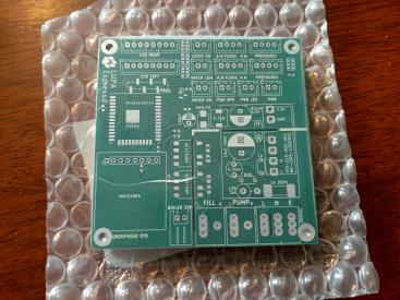
No smoke! And 3.3V on the output!
Though I noticed at the last minute a trace was overlapping between Live and Neutral that definitely would have caused smoke 😬
Next, the low voltage side and crimped connectors and assembling everything together:
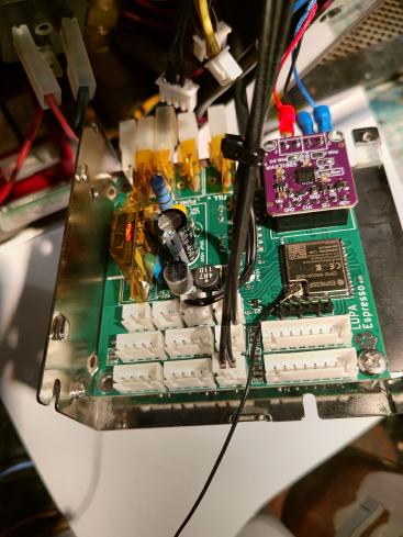
Having an actual crimping tool is a must!
Now, with the cover back on I can finally see it in action:
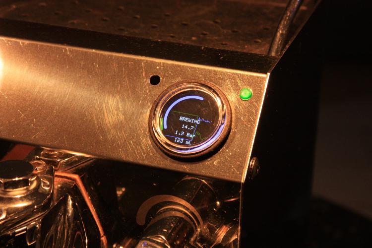
Pulling the lever activates the pump and opens the valve, allowing hot water to flow out the grouphead. The firmware recognizes the flow of water and transitions the UI into brew mode, where it displays the current pressure, volume, and time since the shot was started.
And out flows delicious espresso… ☕