

PicKit2 Unsupported
For my latest project, I foolishly ordered some PIC24FJ256DA206 chips without checking that my programmer actually supported them! So after much pulling of hair, I finally tracked down the problem and realised the chip wasn’t actually supported by my PicKit2.
The PicKit3 can program my chip through MPLABX, but I couldn’t find any in my local stores, and buying one online would have taken weeks to arrive. So I decided to try and see if I could manually add the chips to the PicKit2 GUI.
Why Won’t it Work?
When I attempted to program the chip, PicKit2 just gave me a “Invalid Device ID 0xFFFF” which was strange since usually it would at least report a proper device ID and then say it didn’t support it.
So I dug deeper into the family programmer’s reference manual, then I spotted this buried within:
The address of Special Function Register, TBLPAG, has changed from 0x32 to 0x54 in PIC24FJXXXDA1/DA2/GB2/GA3/GC0 family devices. In those cases where legacy programming specification code from other device families is used as a basis to implement the PIC24FJXXXDA1/DA2/GB2/GA3/GC0 families programming specification, special care must be taken to ensure all references to TBLPAG, in any existing code, are updated with the correct opcode hex data for the mnemonic and operands
This gave me a clue of what I needed to fix, since the PicKit2 actually has a scripting language that appears to actually do all the device-specific work. If they’ve changed that register, then perhaps all the current PIC24 scripts are no longer valid?
Before I investigated that, I decided to figure out how to find the proper parameters when adding a new chip.
The PicKit2 Device File
I have previously used the Device File Editor in this blog post
By comparing a supported PIC24 family by using the PicKit2 Device File Editor and the family’s programming manual, I was able to reverse engineer enough information to be able to add my PIC24F devices. Listed below are the necessary parameters, and how to find them.
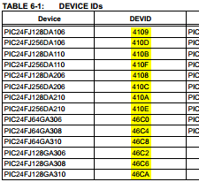
Device ID
This is easily found in both the programmer’s manual (section 6) and the datasheet.
ProgramMem
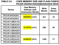
This is also easily found in both the programmer’s manual and the datasheet, however the value found there is actually in bytes, and needs to be converted to instruction words by using the following formula:
ProgramMem = DatasheetValue / 2 + 1
PIC24FJ256DAxxx: ProgramMem = 0x02ABFE / 2 + 1 = 0x15600 words
ConfigAddr
This was a bit trickier, but can be found in the same section as the ProgramMem value, and needs to be converted using the following formula:
ConfigAddr = CONFIGN * 2
Where N is the highest config register (eg. CONFIG4 for my chip)
PIC24FJ256DAxxx: ConfigAddr = 0x2ABF8 * 2 = 0x557F0
ConfigWords
Equal to the number of configuration words!
PIC24FJ256DAxxx: ConfigWords = 4
ConfigMasks
This was trickier to find, and seems to be quite crucial.
Basically find the configuration registers in the device datasheet, set all the reserved bits to 1, and all the other bits to 0. Also duble check the programmer’s reference manual to see if there are any special reserved bits there.
ConfigBlanks
I’m not 100% sure on this, but definitely check the programmer’s reference manual for what values the reserved bits must have. For example, the PIC I’m using requires bit CW1<15> to be set to 0. Note that this doesn’t have to match the mask. If you’re unsure, set it to 0xFFFF and see if that works.
CPConfig
This is for the PicKit2 GUI, it tells it which config register the code-protect bits are located at. It is 1-based, and in reverse order. For my PIC, the code-protect bits are located in CONFIG1, so CPConfig = 4.
CPMask
Related to CPConfig above. Set the code-protect bits to 1 in this mask, so if they are set to 0, the GUI will show a warning.
The PicKit2 Scripting Language
Luckily the PicKit2 GUI source code is available, so I downloaded it and had a shot at making my own script viewer to see if the problem was easily fixable. Since it was written in C#, it was fairly easy to make my own GUI that could read the PicKit2 Device File.
I started by parsing the script against the constants defined in the source code, and found out that some of the scripts were actually executing PIC24 instructions on the device! Looking at the programmer’s manual, I could match some of the byte-codes with the values I was seeing there.
I then added a simple decompiler that supports a few of the opcodes.
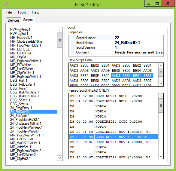
PicKit2 Script Editor & Patcher
The full source code for this is available on github
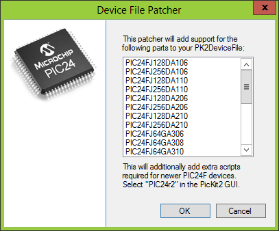
Now that I had everything sorted out and working, I improved the GUI to add a basic device file viewer,and also a patcher that adds support for an entire family of devices! It supports the following chips:
PIC24FJ128DA106, PIC24FJ256DA106, PIC24FJ128DA110, PIC24FJ256DA110, PIC24FJ128DA206, PIC24FJ256DA206, PIC24FJ128DA210, PIC24FJ256DA210, PIC24FJ64GA306, PIC24FJ64GA308, PIC24FJ64GA310, PIC24FJ128GA306, PIC24FJ128GA308, PIC24FJ128GA310, PIC24FJ128GB206, PIC24FJ256GB206, PIC24FJ128GB210, PIC24FJ256GB210, PIC24FJ64GC006, PIC24FJ64GC008, PIC24FJ64GC010, PIC24FJ128GC006, PIC24FJ128GC008, PIC24FJ128GC010
I also added a basic part creator wizard:
And for convenience, you can download my modified PK2DeviceFile.dat which supports all the above chips.
Did it Work?
Yes! My PIC programs fine and verifies!
However, I seem to be having a few problems when the programming executive is enabled; the program memory repeats at address 0x1000 and 0x2000. Disabling the programming executive fixed that though. (Tip: It can be disabled by adding a PICkit2.ini in the PicKit2 GUI folder, running PicKit2 once, and setting PE24: N)
If anyone finds this useful, leave a comment below! If there’s enough interest, I can add more chips to my patcher.
Update: This will also work fine with the PicKit3 GUI! However I can’t seem to find a way to update the MPLABX side of things.