
Introduction
As part of my larger home automation project, I’ve been looking into different options for controlling lighting. There are a number of options available, but I wasn’t satisfied with any of them and I was about to dive into building my own from scratch - until I came across the DALI protocol…
In this post I will discuss the technical operation of the DALI protocol.
Why DALI?
Most residential/commercial lighting uses constant-current power supply modules, and most will support a dimming signal compatible with how an incandescent triac-based dimmer works. In essence the triac dimmer will chop the AC waveform such that the average voltage output is proportional to the dimmer level, much like PWM.
The biggest drawback to this is when you get to very low levels - the AC voltage will tend toward zero, and so the power supply will not be able to continue functioning. Also, chopping the AC waveform means you are susceptible to any fluctuations of the power grid, meaning the brightness may flicker.
Another method developed was to add a second DC signal of 0-10V that controls the brightness directly. This is simple, and solves some of the above problems, but still has a few drawbacks…
The obvious next choice is to use a digital protocol, of which there are a number of choices, all of which solve the above issues:
- DMX512 - Used in theatrical lighting, RS-485
- ArtNet - An ethernet/IP version of DMX512
- KNX - A european open standard for home automation, though not common in the hobbyist world
- DALI - Digital Addressable Lighting Interface
- Zigbee - Wireless protocol that includes support for lighting. Also see Z-wave.
- WiFi - Many avaialble WiFi LED strip drivers, usually based around the ESP32
I would like to avoid wireless protocols, for reliability reasons, so that rules out Zigbee & WiFi solutions. Also the available controllers typically use PWM and so flicker at low frequencies. (unless you use a higher PWM frequency, but then you are spewing EMI everywhere!)
Since DMX/ArtNet is geared more toward theatrical lighting, you don’t find a lot of commercial/residential quality LED drivers available. And actually controlling it is a bit more involved.
KNX seems to be fairly complex to set up from what I’ve read so far, and while it has a lot more capability for non-lighting uses, I haven’t seen as many LED drivers available.
DALI is the only one out of all of these that:
- Has readily available hardware on the market
- Supports flicker-free high dynamic range dimming
- Uses a wired protocol
The DALI standard
DALI v1 supports only simple lamps (which they refer to as “control gear”), while DALI v2 brings in support for sensors (“control device”), switches, colour temperature, and more…
DALI’s biggest downside is that the information on how to implement it is gated behind several standards under IEC-62386, each pay-walled with a >$500 fee!!!
https://www.dali-alliance.org/standards/IEC62386.html
The IEC62386 standards can also be found under AU/NZ standards here (slightly cheaper):
https://www.standards.govt.nz/search/doSearch?Search=62386+
 IEC62386 Overview
I am most interested in driving CCW LED strips, so the standards that are of interest General Requirements (Part 101 & 102), LED Modules (Part 207), and Color Control (Part 209).
To purchase all of these, it would cost me >$1000 NZD 😕
Fortunately you don’t need to purchase any, as there is an open-source Python implementation available here, from which we can determine most of what we need to know:
https://github.com/sde1000/python-dali/
It also offers several options for connecting directly to a DALI bus through a number of available bridges, typically via USB or UART.
In the interests of making DALI more accessible to the hobbyist, the following is a condensed summary of my understanding of the specifications, combined with my personal observations about how the protocol works:
Physical Layer
The DALI bus itself is a 2-wire 1200 baud multidrop bi-directional serial bus using manchester encoding. It is drived by a current-limited 100-250mA 16V supply, which provides power for up to 64 nodes on the bus. (Each node may consume a few mA to drive the optoisolators)
A bus can have one or more lighting devices, and optionally a number of control devices (such as switches or dimmers).
Per the spec, devices are supposed to interface with the bus via optoisolators and a transistor that will short the bus when driven. The current limiter will ensure the voltage drops below a defined threshold without burning anything out. This allows bi-directional communication from multiple devices, and also allows a small amount of power to be provided to devices.
The bare minimum you need to interface with the bus might look like this: (it is not compliant with the spec, but it is a good starting point..)
 Simple bus interface
It operates similarly to CANbus where the bus has a recessive/idle (>9.5V) and dominant/driven state (<6.5V). This allows any node to pull the bus to 0V (logic 1), and the protocol uses this behaviour for initializing addresses much like CAN does (in which the lowest address “wins” when multiple devices drive the bus at the same time, though actual usage here is different).
| Logic | Transmitter | Receiver | Threshold | Typical | Current |
|---|---|---|---|---|---|
| H (Idle) | 11.5 - 20.5V | 9.5 - 22.5V | >9.5V | 16V | <250mA |
| L (Driven) | -4.5 - 4.5V | -6.5 - 6.5V | <6.5V | 0V | <2mA |
Voltages between 6.5V to 9.5V are undefined.
Also, while the spec specifies a nominal voltage of 16V (which is kind of a pain to obtain), in my limited testing the bus works perfectly fine with 12V.
Framing
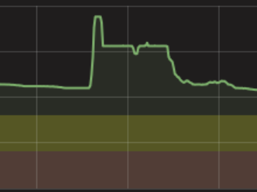
Devices communicate on the bus by transmitting a 1200 baud manchester encoded frame.
 Manchester encoding
DALI communicates with “forward” (command) and “backward” (reply) frames.
A forward frame consists of a start bit, 16 data bits, and a stop bit. A backward frame consists of only 8 data bits:
 Forward and Backward frames
The lowest bit of the address byte (SEL) specifies whether the next byte is a command or “direct brightness control” byte.
A full clock period at 1200 baud is 833μs, but bit transitions occur at a half-clock period of 416μs.
A forward frame will take 15.8ms, and a backward frame will take 9.2ms (excluding the wait time between frames)
Addressing
The DALI bus is addressed using a 7-bit address, which can refer to up to 64 devices, 8 groups, or broadcast to all.
0AAA AAAX : Short address (0-63)
100A AAAX : Group address (0-15)
101C CCC1 : Special commands (broadcast)
110C CCC1 : Special commands (broadcast)
1111 111X : Broadcast
Broadcast addresses can be used to affect every device on the bus at the same time, but cannot receive a meaningful response (due to bus collisions).
Individual device addresses (referred to as the “short address”) must be assigned via a special address initialization procedure.
Some addresses are reserved for use as “special commands”, which are used to affect all devices on the bus at the same time, and free up the 2nd byte to be used for transferring data.
Address assignment procedure
By default, devices will not have a short address assigned, or may come with a hardware address selector.
To assign a short address, we must go through the following sequence:
-
INITIALIZE
In this mode, devices will respond to the next commands we will use. The command must be sent twice, and no response is expected. You can either direct all devices on the bus, a single device, or all devices that do not yet have a short address.
-
RANDOMIZE
This will cause all devices to assign a randomized 24 bit long address (referred to as the “random address”). It is unlikely two devices will get a duplicate address, though if they do, you simply repeat the procedure from 1.
-
COMPARE
Using a binary search algorithm, pick the middle of the address space, and send a COMPARE command to check the programmed SEARCH_ADDR.
All devices that are part of the procedure will respond to this, and return true (0xFF) if they have a random address that is less than or equal to the device you provided. ie,
actual_address <= random_address.Since devices share the bus, any device that responds
true(0xFF) will pull the bus to near 0V, so we will only see afalsehere if NO devices on the bus respond.Putting all of this together, this allows you to determine the lowest address of any device on the bus.
-
WITHDRAW
Withdrawing the address we just identified will remove it from the scan, and will no longer respond to COMPARE.
-
PROGRAM_SHORT_ADDRESS
Assign a new short address.
Only the device that exactly matches the random address we identified above will accept this command.
-
Repeat from step 2 to find the next lowest address
The implementation that I came up with looks like this:
INITIALIZE(0);
RANDOMIZE();

uint8_t short_addr = 0;
while (true) {
    // Find lowest address of any device on the bus
    for (uint32_t i = 0; i < 24; i++) {
        uint32_t bit = 1 << (uint32_t)(23 - i);
        addr |= bit;

        // True if actual address <= search_address
        SET_SEARCH_ADDR(addr);
        if (COMPARE()) {
            addr &= ~bit; // Clear
        } else {
            addr |= bit;  // Set
        }
    }
    SET_SEARCH_ADDR(addr);
    if (!COMPARE()) {
        addr++;
    }

    // Remove this address from the process so it no longer responds to COMPARE
    WITHDRAW(addr);

    // Assign a short address (bit 0 is not part of the address)
    PROGRAM_SHORT_ADDRESS((short_addr++) << 1);

    // Find next lowest address on the bus...
}
Short address must include the 0th bit (DAPC/Command), though it should be set to 0.
A more complete implementation of this can be found in my repository:
esphome-dali/dali_bus_manager.cpp
Brightness Control
Brigthness can be simply set by sending a “Direct Arc Power Control” frame, which requires only 2 bytes.
Bit 0 of the address byte is set to 0 (DAPC), bits 1-7 are the address, and the following byte is an 8-bit brightness value.
Address
┌───────┐
AAAA AAA0 BBBB BBBB
        ↑ └────────┘
      DAPC  Brightness
This brightness value by default is logarithmic, allowing you to span a high range of brightness values.
The DAPC frame can control multiple devices at once via broadcast or group address.
1111 1110 1111 1111 : Set full brightness
1111 1110 0111 1111 : Set 50% brightness (logarithmic)
1111 1110 0000 0000 : Turn off lamp
└───────┘
Broadcast to all
Commands
Commands are sent by setting bit 0 of the address byte, and providing the command in the second byte:
Address     Command ID
┌───────┐    ┌────────┐
AAAA AAA1   CCCC CCCC
        ↑
        Command
If a command is to return false, it will actually be an absence of a response (the device will NOT drive the bus, and timeout is interpreted as a “false” reply).
But some commands will also not return a response at all, in which case you do not need to wait for a timeout.
Example: Turning a lamp off
AAAA AAA1 0000 0000  (CMD_OFF = 0x00)
AAAA AAA1 0000 0000  (CMD_OFF = 0x00)
(no response)
Generally it is recommended to send the command twice, in case the device misses a frame. Some commands require this.
Query
You can query various parameters using the query commands. This follows the same format as above, but you will also expect a response byte, or if you don’t receive a response, then it is treated as false.
If you use a broadcast / group address, multiple devices will drive the bus and the response will be a combination of all of them (where a logic 0 will win over logic 1). This can be used effectively for queries that return a boolean true/false, so if ANY device on the bus returns true, this is what we will receive.
FORWARD FRAME

    Address     Command ID
    ┌───────┐    ┌────────┐
TX: AAAA AAA1   CCCC CCCC
            ↑
            Command

BACKWARD FRAME

    Response byte
    ┌────────┐
RX: RRRR RRRR
Example: Is lamp on?
TX: AAAA AAA1 1001 0011  (QUERY_LAMP_POWER_ON = 0x93)

RX: 1111 1111  -> On
RX: (no reply) -> Off
Special commands
Special commands (such as INITIALIZE or LOAD_DTR0) are actually referenced via the address byte, and the second command byte is used for some optional parameter:
 Command   Data
 ┌──────┐  ┌─────────┐
101C CCC1  DDDD DDDD
110C CCC1  DDDD DDDD
Like above, some commands will return a response, some will not, and “false” is implemented with a timeout.
Since the address byte is used to define these commands, the 2nd byte is free to be used for parameter data, though not all commands use it (in which case it should be set to 0).
Extended device type commands
To implement additional commands for specific device types (eg, RGB control), you must select the device type, then send the device type command:
- ENABLE_DEVICE_TYPE =
device type- sent twice - Send extended command + parameter - sent once
- Optionally read response, if applicable
TX: 1100 0001  0000 0110  : ENABLE_DEVICE_TYPE(0xC1), Device Type = 6 (LED)
TX: 1100 0001  0000 0110  : ENABLE_DEVICE_TYPE(0xC1), Device Type = 6 (LED)
TX: 0AAA AAA1  111C CCCC  : Extended command (224-255)
RX: (optional response byte)
Device Types
| ID | Type |
|---|---|
| 0 | Flurorescent |
| 1 | Emergency Lighting |
| 2 | High Intensity Discharge (HID) |
| 3 | Low Voltage Halogen |
| 4 | Incandescent |
| 5 | Digital |
| 6 | LED |
| 7 | |
| 8 | Colour |
NOTE: I have observed that LED devices with colour support will return device type 6, even though they do also respond to device type 8 commands. I have found that you can use the QUERY EXTENDED VERSION NUMBER (0xFF) extended command to check if a device supports a particular device type feature set.
Data Registers
There are 3 DTR registers defined - DTR0, DTR1, and DTR2.
Since we only have 2 bytes to work with in a frame, to send a configuration value we must first store it in one of these temporary registers, then send a command that will pull the value from the register, much like how assembly instructions work:
TX: 1010 0011 XXXX XXXX (Special command: LOAD DTR0)
TX: AAAA AAA1 CCCC CCCC (Invoke command using value stored in DTR0)
Note that LOAD DTR0 command is a special command and does not take a short address, so all devices on the bus will update their DTR0 register. However devices will only do something with the DTR0 value when instructed to by a second command, which does allow addressing.
| Special Command | ID |
|---|---|
| LOAD_DTR0 | 0xA3 |
| LOAD_DTR1 | 0xC3 |
| LOAD_DTR2 | 0xC5 |
And to read the value of a DTR back via regular query command (value will be in the response byte):
| Command | ID |
|---|---|
| QUERY_CONTENT_DTR0 | 0x98 |
| QUERY_CONTENT_DTR1 | 0x9C |
| QUERY_CONTENT_DTR2 | 0x9D |
Colour Temperature
Setting colour is more complicated as we somehow have to communicate the colour temperature, and the commands are defined in an extended device specification (Part 209 in this case).
The colour temperature is specified as a uint16 in ‘mired ’, which is the inverse of Kelvin.
To set the colour, we must communicate it through the DTR registers, then tell it to start fading to the new temperature with the ACTIVATE command, or a DAPC brightness frame.
- SET DTR0 = lower byte
- SET DTR1 = higher byte
- Send extended command: SET_TEMPERATURE
- Send extended command: ACTIVATE or, send DAPC brightness byte (begins fade)
| Extended Command | Hex ID | Dec ID |
|---|---|---|
| ACTIVATE | 0xE2 | 226 |
| SET_TEMPERATURE | 0xE7 | 231 |
Note step 4 - if you also want to se the brightness, it is importnat that you do NOT send the ACTIVATE command, or it will begin fading the temperature, and be interrupted by the brightness command, and the temperature will not make it to the final value.
This will require 10 forward frames, at 25 ms per frame, or roughly 250ms total. This is an unfortunate downside of the DALI protocol having chosen only 1200 baud.
Groups
Groups can be set by sending the ADD_TO_GROUP command to a specified device. Once set, the device can then be addressed via the group address, much like broadcast.
| Command | ID |
|---|---|
| ADD_TO_GROUP | 60..6F |
| REMOVE_FROM_GROUP | 70..7F |
| QUERY_GROUPS_0_7 | C0 |
| QUERY_GROUPS_8_15 | C1 |
Scenes
Devices (or groups) can set a scene, which stores the current state (brightness, colour, etc) into one of the scene slots. You can then fade to the stored scene by sending the GO_TO_SCENE command.
16 slots are available, selected by adding the scene number to the command ID. ie, to set scene 10, send 0x4A (SET_SCENE).
| Command | ID |
|---|---|
| GO_TO_SCENE | 10..1F |
| SET_SCENE | 40..4F |
| REMOVE_FROM_SCENE | 50..5F |
| QUERY_SCENE_LEVEL | B0..BF |
Appendix
General DALI commands
–           | YAAA AAA0 XXXX XXXX | DIRECT ARC POWER CONTROL
0           | YAAA AAA1 0000 0000 | OFF
1           | YAAA AAA1 0000 0001 | UP
2           | YAAA AAA1 0000 0010 | DOWN
3           | YAAA AAA1 0000 0011 | STEP UP
4           | YAAA AAA1 0000 0100 | STEP DOWN
5           | YAAA AAA1 0000 0101 | RECALL MAX LEVEL
6           | YAAA AAA1 0000 0110 | RECALL MIN LEVEL
7           | YAAA AAA1 0000 0111 | STEP DOWN AND OFF
8           | YAAA AAA1 0000 1000 | ON AND STEP UP
9-15        | YAAA AAA1 0000 1XXX | RESERVED
16 – 31     | YAAA AAA1 0001 XXXX | GO TO SCENE
32          | YAAA AAA1 0010 0000 | RESET
33          | YAAA AAA1 0010 0001 | STORE ACTUAL LEVEL IN THE DTR
34 – 41     | YAAA AAA1 0010 XXXX | RESERVED
42          | YAAA AAA1 0010 1010 | STORE THE DTR AS MAX LEVEL
43          | YAAA AAA1 0010 1011 | STORE THE DTR AS MIN LEVEL
44          | YAAA AAA1 0010 1100 | STORE THE DTR AS SYSTEM FAILURE LEVEL
45          | YAAA AAA1 0010 1101 | STORE THE DTR AS POWER ON LEVEL
46          | YAAA AAA1 0010 1110 | STORE THE DTR AS FADE TIME
47          | YAAA AAA1 0010 1111 | STORE THE DTR AS FADE RATE
48 – 63     | YAAA AAA1 0011 XXXX | RESERVED
64 – 79     | YAAA AAA1 0100 XXXX | STORE THE DTR AS SCENE
80 – 95     | YAAA AAA1 0101 XXXX | REMOVE FROM SCENE
96 – 111    | YAAA AAA1 0110 XXXX | ADD TO GROUP
112 – 127   | YAAA AAA1 0111 XXXX | REMOVE FROM GROUP
128         | YAAA AAA1 1000 0000 | STORE DTR AS SHORT ADDRESS
129 – 143   | YAAA AAA1 1000 XXXX | RESERVED
144         | YAAA AAA1 1001 0000 | QUERY STATUS
145         | YAAA AAA1 1001 0001 | QUERY BALLAST
146         | YAAA AAA1 1001 0010 | QUERY LAMP FAILURE
147         | YAAA AAA1 1001 0011 | QUERY LAMP POWER ON
148         | YAAA AAA1 1001 0100 | QUERY LIMIT ERROR
149         | YAAA AAA1 1001 0101 | QUERY RESET STATE
150         | YAAA AAA1 1001 0110 | QUERY MISSING SHORT ADDRESS
151         | YAAA AAA1 1001 0111 | QUERY VERSION NUMBER
152         | YAAA AAA1 1001 1000 | QUERY CONTENT DTR
153         | YAAA AAA1 1001 1001 | QUERY DEVICE TYPE
154         | YAAA AAA1 1001 1010 | QUERY PHYSICAL MINIMUM LEVEL
155         | YAAA AAA1 1001 1011 | QUERY POWER FAILURE
156 – 159   | YAAA AAA1 1001 11XX | RESERVED
160         | YAAA AAA1 1010 0000 | QUERY ACTUAL LEVEL
161         | YAAA AAA1 1010 0001 | QUERY MAX LEVEL
162         | YAAA AAA1 1010 0010 | QUERY MIN LEVEL
163         | YAAA AAA1 1010 0011 | QUERY POWER ON LEVEL
164         | YAAA AAA1 1010 0100 | QUERY SYSTEM FAILURE LEVEL
165         | YAAA AAA1 1010 0101 | QUERY FADE TIME/FADE RATE
166 – 175   | YAAA AAA1 1010 XXXX | RESERVED
176 – 191   | YAAA AAA1 1011 XXXX | QUERY SCENE LEVEL (SCENES 0-15)
192         | YAAA AAA1 1100 0000 | QUERY GROUPS 0-7
193         | YAAA AAA1 1100 0001 | QUERY GROUPS 8-15
194         | YAAA AAA1 1100 0010 | QUERY RANDOM ADDRESS (H)
195         | YAAA AAA1 1100 0011 | QUERY RANDOM ADDRESS (M)
196         | YAAA AAA1 1100 0100 | QUERY RANDOM ADDRESS (L)
197 – 223   | YAAA AAA1 110X XXXX | RESERVED
224 – 255   | YAAA AAA1 11XX XXXX | QUERY APPLICATION EXTENDED COMMANDS
Special commands:
256         | 1010 0001 0000 0000 | TERMINATE
257         | 1010 0011 XXXX XXXX | DATA TRANSFER REGISTER (DTR)
258         | 1010 0101 XXXX XXXX | INITIALISE
259         | 1010 0111 0000 0000 | RANDOMISE
260         | 1010 1001 0000 0000 | COMPARE
261         | 1010 1011 0000 0000 | WITHDRAW
262         | 1010 1101 0000 0000 | RESERVED
263         | 1010 1111 0000 0000 | RESERVED
264         | 1011 0001 HHHH HHHH | SEARCHADDRH
265         | 1011 0011 MMMM MMMM | SEARCHADDRM
266         | 1011 0101 LLLL LLLL | SEARCHADDRL
267         | 1011 0111 0AAA AAA1 | PROGRAM SHORT ADDRESS
268         | 1011 1001 0AAA AAA1 | VERIFY SHORT ADDRESS
269         | 1011 1011 0000 0000 | QUERY SHORT ADDRESS
270         | 1011 1101 0000 0000 | PHYSICAL SELECTION
271         | 1011 1111 XXXX XXXX | RESERVED
272         | 1100 0001 XXXX XXXX | ENABLE DEVICE TYPE X
273 – 287   | 110X XXX1 XXXX XXXX | RESERVED
Extended commands: LED driver (Part 207)
272         | 1100 0001 0000 0110 | ENABLE DEVICE TYPE 6

224         | YAAA AAA1 1110 0000 | REFERENCE SYSTEM POWER
225         | YAAA AAA1 1110 0001 | ENABLE CURRENT PROTECTOR
226         | YAAA AAA1 1110 0010 | DISABLE CURRENT PROTECTOR
227         | YAAA AAA1 1110 0011 | SELECT DIMMING CURVE (DTR0-> 0:Logarithmic, 1:Linear)
228         | YAAA AAA1 1110 0100 | STORE DTR AS FAST FADE TIME
229-236     |                     | (Reserved...)
237         | YAAA AAA1 1110 1101 | QUERY GEAR TYPE
238         | YAAA AAA1 1110 1110 | QUERY DIMMING CURVE
239         | YAAA AAA1 1110 1111 | QUERY POSSIBLE OPERATING MODES
240         | YAAA AAA1 1111 0000 | QUERY FEATURES
241         | YAAA AAA1 1111 0001 | QUERY FAILURE STATUS
242         | YAAA AAA1 1111 0010 | QUERY SHORT CIRCUIT
243         | YAAA AAA1 1111 0011 | QUERY OPEN CIRCUIT
244         | YAAA AAA1 1111 0100 | QUERY LOAD DECREASE
245         | YAAA AAA1 1111 0101 | QUERY LOAD INCREASE
246         | YAAA AAA1 1111 0110 | QUERY CURRENT PROTECTOR ACTIVE
247         | YAAA AAA1 1111 0111 | QUERY THERMAL SHUT DOWN
248         | YAAA AAA1 1111 1000 | QUERY THERMAL OVERLOAD
249         | YAAA AAA1 1111 1001 | QUERY REFERENCE RUNNING
250         | YAAA AAA1 1111 1010 | QUERY REFERENCE MEASUREMENT FAILED
251         | YAAA AAA1 1111 1011 | QUERY CURRENT PROTECTOR ENABLED
252         | YAAA AAA1 1111 1100 | QUERY OPERATING MODE
253         | YAAA AAA1 1111 1101 | QUERY FAST FADE TIME
254         | YAAA AAA1 1111 1110 | QUERY MIN FAST FADE TIME
255         | YAAA AAA1 1111 1111 | QUERY EXTENDED VERSION NUMBER
Extended commands: Colour (Part 209)
272         | 1100 0001 0000 1000 | ENABLE DEVICE TYPE 8

224         | YAAA AAA1 1110 0000 | SET X COORD VIA DTR0/DTR1
225         | YAAA AAA1 1110 0001 | SET Y COORD VIA DTR0/DTR1
226         | YAAA AAA1 1110 0010 | ACTIVATE
231         | YAAA AAA1 1110 0111 | SET TEMPERATURE VIA DTR0/DTR1
232         | YAAA AAA1 1110 1000 | TEMPERATURE COOLER
233         | YAAA AAA1 1110 1001 | TEMPERATURE WARMER
234         | YAAA AAA1 1110 1010 | SET PRIMARY N DIM LEVEL VIA DTR0/1/2
235         | YAAA AAA1 1110 1011 | SET RGB DIM LEVEL VIA DTR0/1/2/3
236         | YAAA AAA1 1110 1100 | SET WAF DIM LEVEL VIA DTR0/1/2/3
237         | YAAA AAA1 1110 1101 | SET RGBWAF CONTROL VIA DTR0
238         | YAAA AAA1 1110 1110 | COPY REPORT TO TEMPORARY
240         | YAAA AAA1 1111 0000 | STORE TY PRIMARY N VIA DTR0/1/2/3
241         | YAAA AAA1 1111 0001 | STORE XY COORD PRIMARY N VIA DTR2
245         | YAAA AAA1 1111 0101 | ASSIGN TO LINKED CHANNEL VIA DTR0
246         | YAAA AAA1 1111 0110 | START AUTO CALIBRATION
247         | YAAA AAA1 1111 0111 | QUERY GEAR FEATURES
248         | YAAA AAA1 1111 1000 | QUERY COLOR STATUS
249         | YAAA AAA1 1111 1001 | QUERY COLOR FEATURES
250         | YAAA AAA1 1111 1010 | QUERY COLOR VALUE (MSB in response, LSB in DTR0)
251         | YAAA AAA1 1111 1011 | QUERY RGBWAF CONTROL
252         | YAAA AAA1 1111 1100 | QUERY ASSIGNED COLOR (Depends on value in DTR0)
255         | YAAA AAA1 1111 1111 | QUERY EXTENDED VERSION NUMBER

RGBWAF : R, G, B, White, Amber, 'Free Color'
Future Work
Later I will cover the design of a circuit that can interface with a DALI bus, and connect it to ESPHome.
Comments
Note: Comments have been migrated from Disqus to Remark42, a privacy-preserving comment system. (why?)
You can comment anonymously or log in via Github or Email.