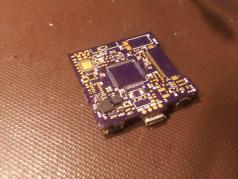
Revision 2
As detailed in my last post about this project , I forgot to make sure that my microcontroller would actually fit the footprint! Since the PCB would need to be completely redone to fit in the new package, I took the opportunity to improve on my previous design.
One change I made was in the power supply; I realised that the MCU can’t operate above 3.6V, and lithium ion batteries supply around 4.3V when fully charged. So I replaced the original MCP73831 lithium ion charger with a BQ25010 which combines a buck regulator with a lithium ion battery charger into a very small package. It actually uses less PCB space than the original lithium ion charging circuit. An LDO may have been a better choice, but I am only aiming for a week or so of battery life in standby, so this chip should be fine.
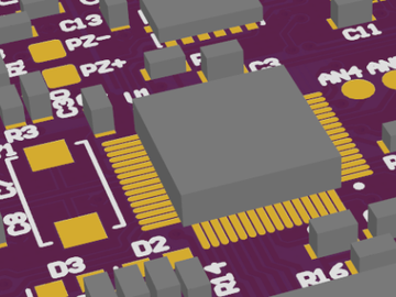
Another addition I made was bluetooth 4.0 (Low Energy), using the nRF8001 chip. I’ve never done RF PCB layout before so I have no idea if it will work, but I wanted to try anyway! There is an open source driver for it already out, and I’ve seen it in a lot of arduino shields too.
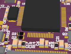
 Routing Last Tracks
Ordering the Parts
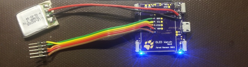
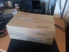
I got three PCBs from OshPark (purple!), and lots of SMD parts from Element14 (Farnell)

I’m not sure what the total cost of this project is, but I don’t care since the main point of it is to learn about building a small low power device with lots of features.
Soldering the PCB
To make sure the design actually worked, I started by soldering just the PIC24F and making sure I could program it, and after that I added the BQ25010 chip. I ran into problems with both of these! I also ended up having to do some patch work since I overlooked some parts of the design, such as the charge enable pin being active low, not active high.
MCU Problems
I spent quite a while pulling my hair out trying to get the PIC to be detected by my PicKit2, but it just wouldn’t register! Eventually I discovered that the PicKit2 didn’t actually support the chip I was using. See my blog post on adding extra devices to the PicKit on how I fixed that.
Luckily all I need to do is program the bootloader, and the rest can be done over USB (which is much faster anyway)
Regulator Problems
Initially the regulator wouldn’t work, it’d produce a very unstable voltage somewhere between 2-4V, so I probed it with an oscilloscope and noticed it was oscillating heavily! Luckily the fix for this was to add a single 100nF capacitor across the battery connection.
Decoupling capacitors are important!!
OLED Problems
I knew I wasn’t going to be able to get this working first try. Unfortunately, I made another huge mistake in my PCB layout… the connector was reversed!! Luckily the connector I was using actually works both ways, so I could get the OLED to work by flipping it. Now it’s on the wrong side of the board, but at least it works!
Interestingly the pinout of the OLED seems to be designed to not be damaged if connected around the wrong way. The +12V pin matches an unconnected pin on the other side.
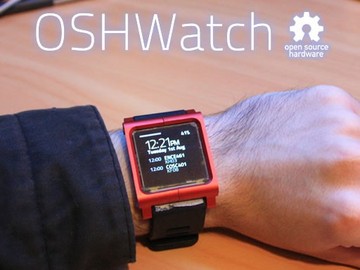
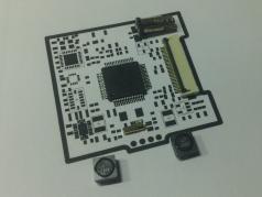
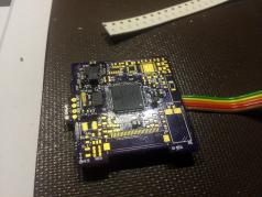
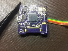
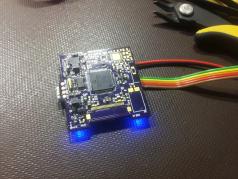
 Success!
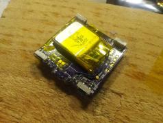
 Taking its final form
 Advanced graphics
I’m getting some strange ghosting problems which I suspect is because I ommitted the VSL pin’s components, but I haven’t really looked into it yet and it doesn’t bother me too much.
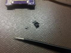
USB Connector Problems
After a few weeks of delicious PIC programming, the USB connector snapped clean off, taking the data traces with it!
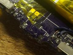
I think the problem here was a combination of using chinese parts, not adding structural holes to the PCB, and not glueing it down. Unfortunately that means I’m stuck using a slow ICSP connection, and don’t have any way to communicate with the device from my PC.
Next Steps
I haven’t been able to work on it lately due to lots of university work (only a few weeks left!), but the next thing I want to do is to shift the components to one of my spare PCBs, so I can have my USB connector back. The OLED connector also started wearing out after flexing it too much, so I might order a new one. Eventually I’d like to 3D print a case for it, but we’ve run out of PLA filament!
I might try design revision 3 as well, and improve from what I’ve learnt on this revision.
I hear e-ink is quite attractive now , and it seems to be something missing from every smart-watch I’ve seen online so far…
Want to know more?
Leave a comment!