
You are likely no stranger to the work-from-home environment many find ourselves in these days, and if you’re like me and have a separate work & play machine but share a single monitor, you will want a KVM to save the hassle of unplugging things at the end of each day.
Unfortunately there don’t seem to be any cheap DisplayPort KVMs out there. The cheapest I could find (at time of writing) was $200USD! Surely something which in theory should be just a high-bandwidth mux shouldn’t cost so much, so I set about creating my own…
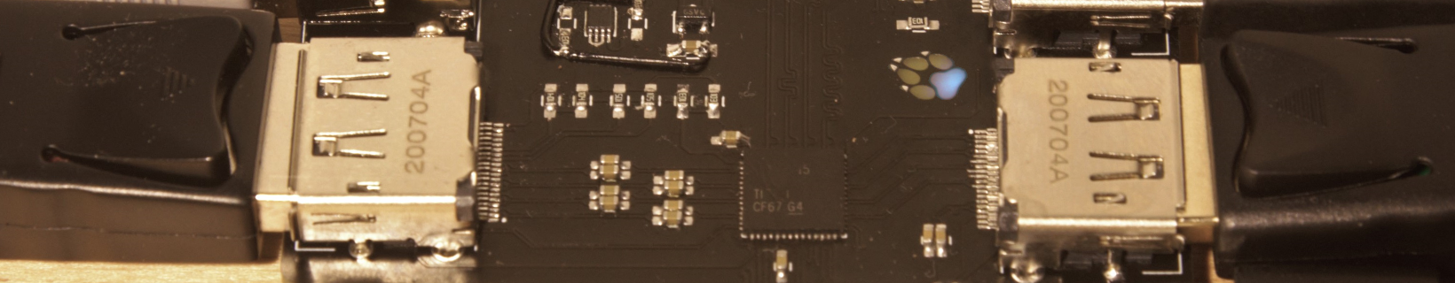
The final hardware is simple and elegant:
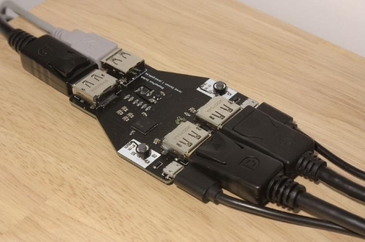
It takes your two DP inputs (plus USB2.0), and with the press of either button you can route either input through to the DP+USB output.

The DP source that gets deactivated simply sees it as if the cable had been unplugged, and the monitor will see it as if you’ve swapped the cable between two machines, and will reconfigure itself accordingly.
This behaviour may cause some minor annoyance as your OS shuffles things around to match the new resolution, but unfortunately the only way to prevent this behaviour would be to write firmware to fake the handshaking to the monitor.
The Design
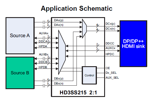
At some point I stumbled upon the Texas Instruments HD3SS215 HDMI/DP 2:1 mux , and at ~$10 a chip it seemed perfect for creating a simple DP switch. It’s very simple on the surface - it allows you to select between two sets of 5 high-speed differential pairs (bi-directional!) with just a single pin.
Now after working with firmware all day for my job , I wasn’t too keen to spend my little free time writing firmware for this (plus I figured I might actually finish it if I kept the scope small…) so I opted to use a simple SR flip-flop circuit and two physical buttons to allow selection of the appropriate output.
This removes the need for any fancy HID-keyboard sniffing, and should be rock-solid since there’s no firmware that can go haywire!
 Flipflop Schematic
 Flipflop Layout
I also wanted to switch a USB2.0 keyboard and mouse which would normally necessitate another mux chip, but I saw that the HD3SS215 had mux lines to support both DP & HDMI side-band signals, and since I wasn’t supporting HDMI I figured I could probably abuse these to switch USB2.0. Unfortunately the datasheet didn’t indicate what speed these signals were rated for, so I just winged it and hoped it would work in my prototype… fortunately it seems to work fine.
Now the trickiest part of the design is the high-speed DisplayPort signals which operate in the GHz range. This requires careful routing and impedance-controlled layout. Fortunately this has become easier in the latest Kicad with the addition of differential signal tools.
 Differential Routing
Rev1 Mistakes
No project is perfect from the start - in my first prototype I encountered a few major issues:
- The flip-flop circuit’s inputs were inverted (I neglected to note that the inputs need to be active-low)
- The USB input connectors were flipped in respect to the DP input connectors. Oops.
- The DP connectors are a bit sloppy, and if you move the cable the signal will drop out breifly.
These issues have been corrected (but not tested) in the latest version on Github.
Additionally, I added extra test points and 0R resistors in Rev2 to allow for reconfiguration of the DDC/AUX lines, in case I want to make it smarter in the future.
Manufacturing
You are free to build your own!
The design files are licensed under the CERN OHL-S v2 license, which states that you can modify the design as long as you keep the terms of the original license and make your changes available (similar to GPL). You are also free to sell it, but I ask that you retain attribution on the silkscreen.
Now that you understand the above disclaimer, you can find the full KiCad sources on GitHub .
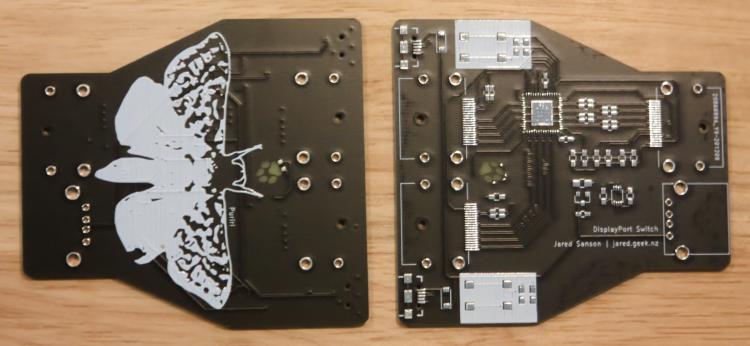
Since DP operates in the GHz range, the PCB must be impedance controlled, and requires a 4 layer stackup. I used JLCPCB’s 4-layer ‘JLC7628 ’ PCB with a dielectric constant of 4.6, and a black solder mask.
It should be relatively straight forward to solder if you have any experience with 0603 resistors and QFN parts. It should be easily achievable with a hotplate, hot air gun, or reflow oven.
That being said, I was not immediately successful when soldering with a hotplate - one of the DP channels didn’t work at first, but I was able to resolve it by reflowing the solder on the QFN chip and DP connector. If you encounter similar issues, try reflowing things, and watch out for solder bridges!!
If you do end up building this, let me know in the comments